

In the realm of electrical engineering and power management, current sensors play a pivotal role. They are essential components used to measure electrical current accurately in various applications, from industrial automation to renewable energy systems. One crucial characteristic of a current sensor is its impulse response. As a current sensor supplier, I am excited to delve into the concept of the impulse response of a current sensor, exploring its significance, how it works, and its impact on real - world applications.
Understanding the Basics of Current Sensors
Before we dive into the impulse response, let's briefly understand what a current sensor is. A current sensor is a device that detects and measures the flow of electrical current in a circuit. There are different types of current sensors, such as Hall - effect sensors, shunt resistors, and Rogowski coils, each with its own working principle and set of advantages.
Hall - effect sensors, for example, use the Hall effect to measure current. When a current - carrying conductor is placed in a magnetic field, a voltage is generated perpendicular to both the current and the magnetic field. This voltage can be measured and used to determine the magnitude of the current. Shunt resistors, on the other hand, measure current by passing it through a low - resistance resistor and measuring the voltage drop across it, based on Ohm's law (V = IR).
What is Impulse Response?
The impulse response of a system, including a current sensor, is the output of the system when it is subjected to an impulse input. An impulse input is an idealized signal that has an infinitely short duration and an infinitely large amplitude, with an area under the curve equal to 1. In practical terms, an impulse can be approximated by a very short - duration, high - amplitude pulse.
When an impulse is applied to a current sensor, the sensor's output over time is its impulse response. This response provides valuable information about the sensor's behavior, such as its speed of response, its ability to accurately reproduce the input signal, and its stability.
Significance of Impulse Response in Current Sensors
The impulse response of a current sensor is of great significance for several reasons. Firstly, it helps in understanding the sensor's dynamic performance. In many applications, the current in a circuit can change rapidly, for example, during the startup or shutdown of a power system, or when there are sudden load changes. A current sensor with a fast and accurate impulse response can quickly and precisely measure these rapid changes in current, ensuring that the control system can respond appropriately.
Secondly, the impulse response is related to the sensor's bandwidth. The bandwidth of a current sensor is the range of frequencies over which the sensor can accurately measure the current. A sensor with a good impulse response typically has a wider bandwidth, which means it can handle higher - frequency current variations. This is crucial in applications such as high - speed power electronics, where the current can have high - frequency components.
Measuring the Impulse Response of a Current Sensor
Measuring the impulse response of a current sensor involves applying a short - duration, high - amplitude pulse to the sensor and recording its output over time. This can be done using specialized test equipment, such as a pulse generator and an oscilloscope.
The test setup usually consists of a pulse generator that generates the impulse input, which is then applied to the current sensor. The output of the current sensor is connected to an oscilloscope, which can display and record the sensor's output waveform. By analyzing the output waveform, we can determine the key characteristics of the impulse response, such as the rise time, fall time, and overshoot.
The rise time is the time it takes for the sensor's output to rise from a specified low value (usually 10% of the final value) to a specified high value (usually 90% of the final value). A shorter rise time indicates a faster - responding sensor. The fall time is the time it takes for the output to fall from 90% to 10% of the final value. Overshoot is the amount by which the output exceeds the final steady - state value before settling down.
Factors Affecting the Impulse Response of a Current Sensor
Several factors can affect the impulse response of a current sensor. One of the main factors is the sensor's internal circuitry. For example, in a Hall - effect current sensor, the design of the Hall element, the signal conditioning circuit, and the amplifier can all influence the sensor's impulse response. A well - designed signal conditioning circuit can help to reduce noise and improve the sensor's response speed.
The physical construction of the sensor also plays a role. The size and shape of the sensor, as well as the materials used, can affect its magnetic properties and electrical characteristics, which in turn can impact the impulse response. For instance, a sensor with a smaller physical size may have a faster response time due to reduced parasitic capacitance and inductance.
Another factor is the load connected to the sensor. The impedance of the load can affect the sensor's output and its impulse response. A load with a high impedance may cause the sensor's output to have a longer settling time, while a low - impedance load may cause excessive current draw and affect the sensor's accuracy.
Real - World Applications and the Role of Impulse Response
In real - world applications, the impulse response of a current sensor can have a significant impact on the performance of the overall system. For example, in electric vehicle (EV) charging stations, the current sensor needs to accurately measure the charging current, which can change rapidly during the charging process. A current sensor with a good impulse response can ensure that the charging process is safe and efficient, by quickly detecting any abnormal current changes and triggering appropriate protective measures.
In renewable energy systems, such as solar and wind power plants, current sensors are used to monitor the power output of the generators. The current in these systems can vary rapidly due to changes in weather conditions or grid demand. A current sensor with a fast impulse response can help in optimizing the power generation and distribution, by providing accurate and timely current measurements.
Example: LEM CAB500C 12V CAB500 Current Sensor
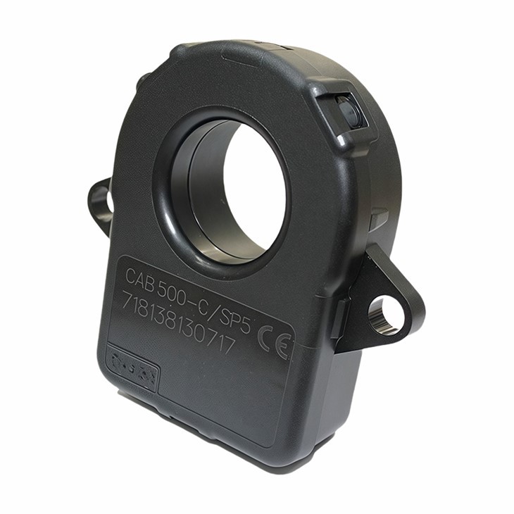
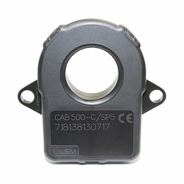
One example of a high - performance current sensor is the LEM CAB500C 12V CAB500 Current Sensor. This sensor is designed to provide accurate current measurements in a wide range of applications. Its impulse response characteristics make it suitable for applications where rapid current changes need to be detected. The sensor has a fast rise time and low overshoot, which means it can quickly and accurately respond to impulse inputs, ensuring reliable performance in dynamic systems.
Conclusion and Call to Action
In conclusion, the impulse response of a current sensor is a critical characteristic that determines its dynamic performance, bandwidth, and suitability for various applications. As a current sensor supplier, we understand the importance of providing sensors with excellent impulse response characteristics. Our sensors are designed and tested to ensure that they can meet the demanding requirements of modern electrical systems.
If you are in need of high - quality current sensors for your projects, whether it's for industrial automation, renewable energy, or electric vehicle applications, we are here to help. We offer a wide range of current sensors with different specifications and impulse response characteristics to suit your specific needs. Contact us today to start a discussion about your current sensor requirements and explore how our products can enhance the performance of your systems.
References
- Dorf, R. C., & Bishop, R. H. (2016). Modern Control Systems. Pearson.
- Mohan, N., Undeland, T. M., & Robbins, W. P. (2012). Power Electronics: Converters, Applications, and Design. Wiley.